Reverse Osmosis (RO) stands as a pivotal technology in modern water purification, effectively eliminating a vast array of contaminants from water. This process involves forcing water through a semi-permeable membrane under pressure, resulting in highly purified water. This article provides an in-depth exploration of Reverse Osmosis technology, detailing its mechanisms, applications, and significance in ensuring access to clean water.
Osmosis and Reverse Osmosis: The Core Principles
To fully grasp the concept of Reverse Osmosis, it’s essential first to understand osmosis, the natural phenomenon upon which RO is based.
Osmosis Explained
Osmosis is a naturally occurring process vital to numerous biological and environmental systems. It describes the movement of a solvent, typically water, across a semi-permeable membrane from an area of lower solute concentration to an area of higher solute concentration. This movement aims to equalize the solute concentrations on both sides of the membrane. Think of plant roots absorbing water from the soil or our kidneys filtering water from our blood – both are examples of osmosis in action.
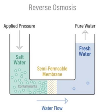
Imagine two compartments separated by a semi-permeable membrane. One compartment contains pure water, and the other contains a saltwater solution. Due to osmosis, the pure water will naturally flow into the saltwater compartment to dilute it, until equilibrium is achieved.
A semi-permeable membrane is key to this process. It’s designed to allow certain molecules to pass through while blocking others. A kitchen sieve is a rudimentary example – it allows water to pass but retains larger solids. More sophisticated examples include specialized films with microscopic pores that selectively permit water molecules while blocking larger contaminants.
The Reverse Osmosis Process
Reverse Osmosis, as the name suggests, is osmosis in reverse. Unlike natural osmosis, RO requires external energy to overcome osmotic pressure and force water flow in the opposite direction – from a high solute concentration area to a low solute concentration area.
In RO, pressure is applied to the more concentrated solution, forcing water molecules through a semi-permeable membrane. This membrane is specifically engineered to allow water molecules to pass through while rejecting the vast majority of dissolved salts, organic matter, bacteria, and pyrogens. This process effectively separates purified water from contaminants.
By applying pressure exceeding the osmotic pressure, the natural osmotic flow is reversed. Water molecules are pushed through the RO membrane, leaving behind contaminants. This results in two streams: purified water (permeate) and concentrated contaminants (concentrate).
How Reverse Osmosis Systematically Purifies Water
Reverse Osmosis systems employ a high-pressure pump to increase the pressure on the feedwater, forcing it against the RO membrane. This pressure must be significant enough to overcome the osmotic pressure and drive water molecules through the membrane. Typically, RO systems can remove 95% to 99% of dissolved salts from the feedwater.
The pressure required for effective RO operation is directly related to the salinity of the feedwater. Higher salt concentrations necessitate greater pressure to achieve purification.
Permeate and Concentrate: Understanding the Output Streams
In simplified terms, an RO system takes in feedwater and produces two output streams: permeate and concentrate.
Permeate (Product Water): This is the purified water that has successfully passed through the RO membrane. It’s significantly lower in contaminants and is often referred to as product water. The capacity of an RO system is typically measured by its permeate flow rate, for example, a 100 gallons per minute (gpm) RO system produces 100 gpm of permeate.
Concentrate (Reject or Brine): This stream contains the concentrated contaminants that were rejected by the RO membrane. It is also known as reject or brine. These terms are interchangeable and refer to the wastewater stream carrying the concentrated impurities. Depending on regulations and water scarcity, the concentrate may be discharged or, in some cases, recycled back into the system to enhance water recovery.
As feedwater is pressurized and enters the RO membrane, water molecules are driven through, while salts and other contaminants are left behind. These rejected contaminants are then flushed out of the system via the concentrate stream. The permeate, having passed through the membrane, is substantially purified, typically with a 95% to 99% reduction in dissolved salts.
A crucial aspect of RO systems is their use of cross-filtration. Unlike conventional dead-end filtration where contaminants accumulate within the filter media, cross-filtration directs the feedwater across the membrane surface. This creates two outlets: one for the purified permeate and another for the contaminant-rich concentrate. This cross-flow action helps to sweep away contaminant buildup and maintain membrane surface cleanliness.
Spectrum of Contaminants Removed by Reverse Osmosis
Reverse Osmosis is exceptionally effective at removing a wide spectrum of contaminants, typically eliminating 95-99% of dissolved salts (ions), particles, colloids, organics, bacteria, and pyrogens from feedwater. The RO membrane’s rejection capability is primarily based on contaminant size and charge. Substances with a molecular weight exceeding 200 are highly likely to be rejected by a properly functioning RO system.
Ionic charge also plays a significant role in contaminant rejection. Ions with a higher charge are more effectively rejected. For instance, calcium, with its double charge (divalent), is rejected more effectively than sodium, which has a single charge (monovalent).
However, RO systems are less effective at removing dissolved gases, such as carbon dioxide (CO2). This is because gases are not highly ionized in solution and have a very low molecular weight. Consequently, permeate water from an RO system may have a slightly lower pH than normal, depending on the CO2 levels in the feedwater, as CO2 converts to carbonic acid.
RO technology is widely applicable for treating various water sources, including brackish water, surface water, and groundwater, for both large-scale industrial needs and smaller applications. Industries heavily reliant on RO purified water include pharmaceuticals, boiler feedwater, food and beverage production, metal finishing, and semiconductor manufacturing, among others.
Evaluating RO System Performance: Key Metrics and Calculations
Several key calculations are used to assess the efficiency and performance of an RO system and are essential for system design and monitoring. Modern RO systems are equipped with instrumentation to display parameters such as water quality (conductivity), flow rates, pressure, and sometimes temperature and operational hours. To accurately evaluate RO system performance, the following operational parameters are essential:
- Feed pressure
- Permeate pressure
- Concentrate pressure
- Feed conductivity
- Permeate conductivity
- Concentrate flow rate
- Permeate flow rate
- Temperature
Salt Rejection Percentage
This metric quantifies the RO membranes’ effectiveness in removing contaminants. It provides an overall system performance indicator, reflecting the average performance of all membranes collectively.
A well-designed and maintained RO system should achieve a salt rejection rate of 95% to 99% for most feedwater contaminants (within a certain size and charge range).
The formula to calculate salt rejection percentage is:
Salt Rejection % = ((Feed water conductivity – Permeate water conductivity) / Feed water conductivity) x 100
Salt Passage Percentage
Salt passage percentage is the inverse of salt rejection. It represents the percentage of salts that pass through the RO system. Lower salt passage percentages indicate better system performance. An increase in salt passage may signal the need for membrane cleaning or replacement.
Salt Passage % = (1 – Salt Rejection %) x 100
Recovery Percentage
Recovery percentage indicates the proportion of feedwater that is converted into purified permeate water. It reflects the system’s efficiency in water usage. A higher recovery percentage means less water is wasted as concentrate and more is recovered as usable permeate. However, excessively high recovery rates can lead to scaling and fouling issues if not properly managed within the RO system’s design parameters.
RO system design software determines optimal recovery rates based on feedwater chemistry and pretreatment processes. Deviations from the designed recovery rate can indicate operational issues.
% Recovery = (Permeate Flow Rate gpm / (Permeate Flow Rate gpm + Concentrate Flow Rate gpm)) x 100
For example, an 80% recovery rate means that for every 100 gallons of feedwater, 80 gallons are recovered as permeate, and 20 gallons become concentrate. Commercial RO systems typically operate at recovery rates between 50% and 85%, depending on feedwater characteristics and system design.
Concentration Factor
The concentration factor is closely linked to the recovery rate and is crucial for RO system design. Higher recovery rates lead to a greater concentration of salts and contaminants in the concentrate stream. If the concentration factor exceeds the system’s design limits or feedwater composition, it can increase scaling on membrane surfaces.
Concentration Factor = (1 / (1 – Recovery %))
This factor helps predict the level of contaminant concentration in the concentrate stream. For example, an 80% recovery rate results in a concentration factor of 5, meaning the concentrate stream is five times more concentrated than the feedwater. If the feedwater has 500 ppm of dissolved solids, the concentrate stream will have 2,500 ppm.
Flux
Flux measures the rate of water permeation through the RO membrane, typically expressed in gallons per square foot per day (GFD) or liters per square meter per hour (l/m²/hr). A higher flux indicates a greater volume of water passing through the membrane area in a given time.
RO system designers aim to maintain flux within a specific range to ensure optimal membrane performance. Flux that is too high or too low can negatively impact membrane life and efficiency.
Flux Gfd = (Permeate flow gpm * 1,440) / (# of RO elements in system * square footage of each RO element)
For example, an RO system producing 80 gpm of permeate with 18 RO membranes, each having 400 square feet of surface area, would have a flux of approximately 16 Gfd.
Recommended flux ranges vary based on the feedwater source:
| Feed Water Source | Gfd Flux |
|---|---|
| RO Permeate Water | 20-30 |
| Brackish Well Water | 14-18 |
| Brackish Surface Water | 10-14 |
| Sea Water | 8-12 |
| Sewage Effluent | 5-10 |
Stages and Passes in Reverse Osmosis Systems
The terms ‘stage’ and ‘pass’ are often used in the context of RO systems and, while related, describe different aspects of system configuration. Understanding the distinction between one- and two-stage RO systems and single-pass versus double-pass RO systems is important for system design and operation.
One-Stage vs. Two-Stage RO Systems
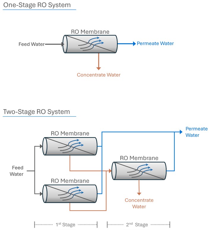
One-Stage RO System: In a single-stage system, feedwater flows through a set of RO membranes in a single pass. The system produces permeate and concentrate in a single step.
Two-Stage RO System: A two-stage system increases water recovery. The concentrate from the first stage becomes the feedwater for the second stage. Permeate from both stages is collected, while the final concentrate from the second stage is discharged. This configuration enhances overall system recovery by further processing the reject stream from the first stage.
Array Configurations
In multi-stage RO systems, the ‘array’ describes the physical arrangement of pressure vessels holding the RO membranes. For instance, a 2:1 array in a two-stage system means the concentrate from two pressure vessels in the first stage is fed into one pressure vessel in the second stage.
Concentrate Recycle
When system staging is not feasible or feedwater chemistry allows, concentrate recycle can be employed. A portion of the concentrate stream is recirculated back to the feedwater inlet of the first stage to improve system recovery.
Single-Pass vs. Double-Pass RO Systems
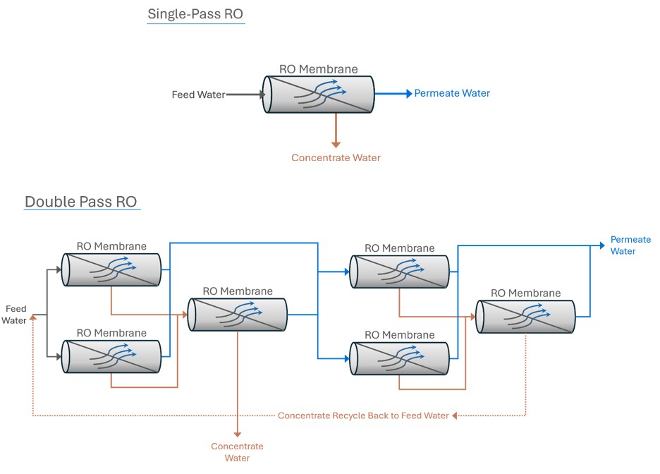
Single-Pass RO System: In a single-pass system, water passes through the RO membranes only once.
Double-Pass RO System: A double-pass system significantly enhances permeate quality. The permeate from the first pass (first RO system) becomes the feedwater for the second pass (second RO system). This double treatment results in exceptionally high purity water.
Double-pass RO systems also facilitate the removal of carbon dioxide (CO2). By injecting caustic between the first and second pass, the pH of the first-pass permeate is raised, converting CO2 to bicarbonate (HCO3-) and carbonate (CO3-2), which are more effectively rejected by RO membranes in the second pass. This CO2 removal is particularly beneficial when using mixed bed ion exchange resins for post-RO polishing.
The Critical Role of RO Pretreatment
Effective pretreatment is paramount for the longevity and efficiency of RO systems. Proper pretreatment minimizes fouling, scaling, chemical attack, and mechanical damage, preventing premature membrane failure and reducing the frequency of membrane cleaning. Common issues arising from inadequate pretreatment are detailed below:
Fouling
Fouling occurs when contaminants accumulate on the membrane surface, obstructing water flow and reducing performance. Common foulants include particulate matter, colloidal substances, organics, and microorganisms. Bacteria are a frequent cause of fouling as RO membranes cannot tolerate disinfectants, allowing biofilms to develop and heavily foul membranes. Fouling leads to reduced permeate flow and increased pressure drop, raising operating costs and necessitating membrane cleaning or replacement. Pretreatment strategies, such as multi-media filters or microfiltration, are essential to minimize fouling.
Scaling
Scaling is the precipitation of dissolved inorganic compounds on the membrane surface when their concentration exceeds solubility limits. Common scale-forming compounds include calcium carbonate. Scaling results in increased pressure drop, higher salt passage, and reduced permeate flow. Managing concentration factors and employing antiscalants are crucial for scale prevention.
Chemical Attack
Modern thin-film composite RO membranes are vulnerable to oxidation from chlorine and chloramines. Oxidizing agents can damage membranes, leading to increased permeate flow but also higher salt passage and reduced rejection. Pretreatment methods like sodium bisulfite dosing or granular activated carbon filtration are used to remove oxidizers.
Mechanical Damage
Mechanical damage can result from sudden pressure surges (hard starts) or excessive backpressure. Variable frequency drives for high-pressure pumps and pressure relief valves are used to mitigate mechanical stress and protect membranes.
Pretreatment Solutions for RO Systems
Various pretreatment technologies are employed to address the challenges of fouling, scaling, and chemical attack and ensure optimal RO system performance.
Multi-Media Filters (MMF)
Multi-Media Filters are effective in removing particulate matter and preventing fouling. They typically consist of layers of anthracite coal, sand, and garnet, arranged to capture progressively smaller particles throughout the filter bed. MMFs can remove particles down to 15-20 microns and, with coagulant addition, down to 5-10 microns. They are recommended when feedwater Silt Density Index (SDI) exceeds 3 or turbidity exceeds 0.2 NTU. A 5-micron cartridge filter is often placed downstream of the MMF to capture any media carryover.
Microfiltration (MF)
Microfiltration is used to remove colloidal matter and bacteria, further reducing fouling potential. MF membranes have pore sizes of 0.1-10µm and are often used in a hollow fiber configuration with dead-end flow and periodic backwashing.
Antiscalants and Scale Inhibitors
Antiscalants are chemicals added to feedwater to increase the solubility limits of scale-forming compounds, thus preventing scaling. They interfere with scale formation and crystal growth, allowing for higher recovery rates and concentration factors.
Water Softening
Water softeners can be used to remove scale-forming ions, replacing them with non-scale-forming ions. A downstream 5-micron cartridge filter is also recommended after water softeners to prevent media carryover.
Sodium Bisulfite (SBS)
Sodium bisulfite is a reducing agent used to neutralize chlorine and chloramines in feedwater, protecting membranes from chemical attack.
Granular Activated Carbon (GAC)
Granular Activated Carbon effectively removes organics and residual disinfectants like chlorine and chloramines through chemical reaction and adsorption. However, GAC beds can become breeding grounds for bacteria and may release carbon fines. A cartridge filter is recommended downstream of GAC to capture carbon fines.
RO Data Monitoring and Performance Normalization
Regular monitoring of RO system data is crucial for assessing membrane health and system performance. Key data points include pressures, flows, conductivity, and temperature. Water temperature significantly affects RO performance; lower temperatures increase viscosity and reduce permeate flow, while higher temperatures increase flow. Data normalization accounts for temperature variations, providing a more accurate assessment of membrane performance.
Normalized data, including flows, pressures, and salt rejection, should be compared to baseline data (collected during commissioning or after membrane cleaning). Deviations of +/- 15% from baseline often indicate the need for membrane cleaning or inspection.
Data normalization helps to distinguish between performance changes due to operational issues versus normal fluctuations due to temperature.
RO Membrane Cleaning Procedures
Periodic cleaning of RO membranes is essential, typically required 1-4 times per year depending on feedwater quality. Cleaning is indicated by a normalized pressure drop or salt passage increase of 15%, or a normalized permeate flow decrease of 15%. Membranes can be cleaned in place or off-site by specialized service providers. Off-site cleaning is generally more effective.
RO membrane cleaning involves using both low-pH cleaners to remove scale and high-pH cleaners to remove organics, colloidal matter, and biofouling. Proper cleaning requires expertise, appropriate chemicals, controlled flows, temperatures, and specialized cleaning skids to prevent membrane damage.
Conclusion: Reverse Osmosis as a Cornerstone of Water Purification
Reverse Osmosis is a highly effective and widely used technology for removing a broad spectrum of contaminants from water. It is a cornerstone of modern water purification, providing high-purity water for diverse applications. Post-RO treatments like mixed bed deionization can further enhance permeate quality for ultra-pure water needs. Proper pretreatment, diligent system monitoring, and expert maintenance are essential for ensuring the long-term, reliable performance of RO systems. With appropriate design, maintenance, and support, RO systems deliver consistently high-quality water for years.