The Controller Area Network (CAN) bus is a robust communication protocol widely used in vehicles and industrial automation. It allows various electronic control units (ECUs) to communicate with each other without a central host computer. This guide provides a detailed explanation of the CAN bus, including its architecture, benefits, history, and future trends.
Imagine a car as a complex organism. The CAN bus functions like the nervous system, enabling seamless communication between different parts. ECUs, such as the engine control unit, brakes, and transmission, act as individual organs interconnected by this network. Information sensed by one ECU can be quickly and reliably shared with others, enhancing overall system performance and safety.
Physically, the CAN bus consists of a two-wire twisted pair: CAN High and CAN Low, often color-coded yellow and green respectively. All ECUs are connected to these wires, enabling them to send and receive data.
Automotive car showcasing a CAN bus system connecting various electronic control units (ECUs).
Understanding ECUs in the CAN Bus
An ECU, or Electronic Control Unit, is a specialized component that controls a specific function within a system. In a modern vehicle, you might find over 70 ECUs managing everything from the engine and transmission to the brakes, steering, and climate control.
Each ECU on the CAN bus has the ability to prepare and broadcast data, such as sensor readings. All other ECUs on the network receive this broadcast and decide whether to accept or ignore the data based on its relevance to their specific function.
Zooming in on an individual ECU, we can identify three primary elements:
- Microcontroller (MCU): The MCU is the brain of the ECU. It interprets incoming CAN messages and decides which messages to transmit. For example, a sensor might be programmed to measure and broadcast oil temperature at a specific frequency.
- CAN Controller: Typically integrated into the MCU, the CAN controller handles the complexities of the CAN protocol, including message encoding, error detection, and arbitration. This offloads processing overhead from the MCU.
- CAN Transceiver: The CAN transceiver acts as an interface between the CAN controller and the physical CAN bus wires. It converts data from the controller into differential signals suitable for transmission over the CAN bus and vice versa, while also providing electrical protection.
Illustration of an electronic control unit (ECU) within a CAN bus network, highlighting its key components.
Connecting to the CAN Bus: The DB9 Connector
While there isn’t a universal standard connector for CAN bus applications, the CAN DB9 (D-sub9) connector (CANopen CiA 303-1) has emerged as a popular choice, particularly for CAN bus data loggers and interfaces. However, it’s important to note that different vehicles and machines may utilize different connector types.
Diagram showing the pinout configuration of a CAN bus DB9 connector, a common interface for data loggers.
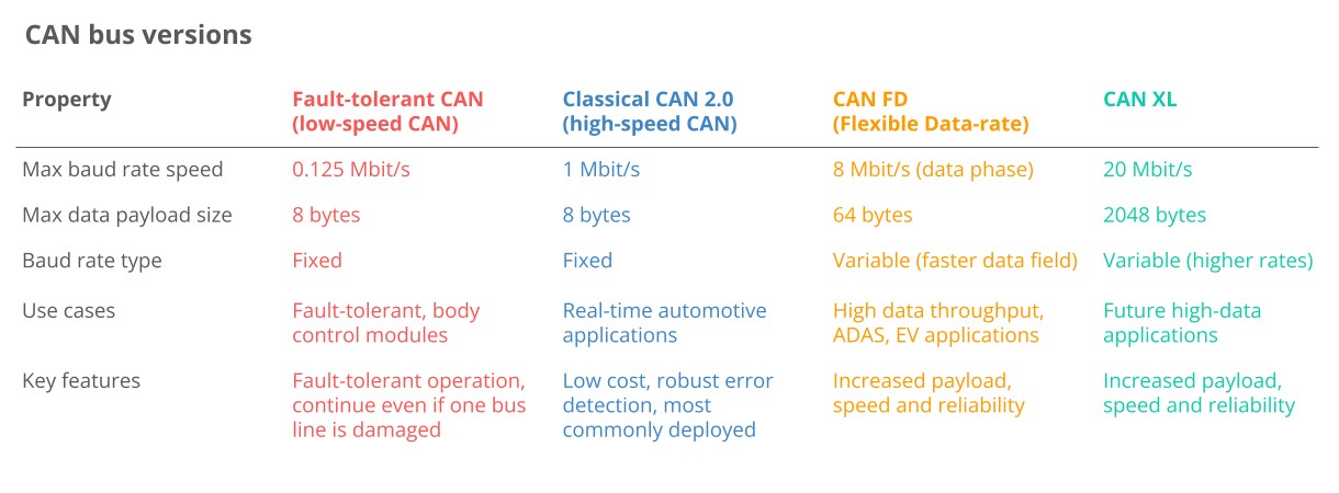
CAN Bus Variants
Several variants of CAN exist, each with its own strengths and weaknesses:
- Low-Speed CAN (Fault-Tolerant CAN): A cost-effective option when fault tolerance is critical. However, it is increasingly being replaced by LIN bus.
- High-Speed CAN (Classical CAN): The most common variant in automotive and machinery applications today. This article primarily focuses on Classical CAN.
- CAN FD (CAN Flexible Data-Rate): Offers longer payloads and faster speeds compared to Classical CAN, but adoption remains somewhat limited.
- CAN XL: Designed to bridge the gap between CAN and Automotive Ethernet by offering even longer payloads and faster speeds.
In automotive applications, other non-CAN networks are also commonly found:
- LIN Bus: A lower-cost complement to CAN bus, typically used for non-critical vehicle functions like air conditioning and door controls.
- FlexRay: Offers higher speeds, fault tolerance, and flexibility compared to CAN, but is also more expensive.
- Automotive Ethernet: Increasingly used to support the high bandwidth requirements of advanced driver-assistance systems (ADAS), infotainment, and cameras.
Key Benefits of CAN Bus
The CAN bus standard is widely adopted across various industries due to its numerous advantages:
-
Simplicity and Low Cost: ECUs communicate via a single CAN system instead of complex, direct analog signal lines, reducing wiring, weight, and costs.
- Reduced Wire Complexity: Traditional point-to-point wiring requires dedicated wires between each node, increasing costs and reducing flexibility.
- Weight Reduction: Switching to CAN bus can reduce the weight of a vehicle’s wiring harness by up to 20 kg, leading to fuel savings.
- Scale: The popularity of CAN reduces the cost of controllers, transceivers, harnesses, and related equipment.
Illustration representing the cost-effectiveness of the CAN bus system compared to traditional wiring methods.
-
Easy Access: The CAN bus provides a single point of entry to communicate with all network ECUs, enabling centralized diagnostics, data logging, and configuration.
- Centralized Diagnostics: Connect an interface anywhere on the CAN bus to access 100% of the traffic, simplifying diagnostics.
- Silent CAN Logging: CAN bus data logging can be performed in ‘silent mode’ without affecting the CAN bus, critical for diagnostics.
- ECU Flashing: Update any ECU on the network by transmitting firmware updates as CAN frames.
- Standardization: Standardized higher-layer protocols enhance the interoperability of hardware and software tools.
Visual representation of the centralized data logging and diagnostic capabilities offered by the CAN bus architecture.
-
Extreme Robustness: The system is highly resistant to electrical disturbances and electromagnetic interference, making it suitable for safety-critical applications.
- Differential Signaling: Electromagnetic interference (EMI) affects both lines in the CAN bus equally, making the differential signal robust against environmental noise.
- Error Handling: CAN ensures data integrity through extensive error detection mechanisms, including bit errors, stuff errors, CRC errors, form errors, and ACK errors. Nodes can automatically retransmit faulty messages.
- Confinement: CAN nodes track their own errors and can temporarily or permanently disconnect from the bus if error thresholds are exceeded, preventing bus jamming.
Depiction of the CAN bus’s robust design, showcasing its resistance to electromagnetic interference.
-
Efficiency: CAN frames are prioritized by ID, allowing high-priority data to gain immediate bus access without interrupting other frames or causing errors.
- Arbitration: When multiple CAN nodes attempt to transmit data simultaneously, the frame with the lowest CAN ID (highest priority) wins, while others back off and retry.
- Utilization: Arbitration ensures efficient use of CAN bus bandwidth by ‘filling gaps’ between critical messages with lower-priority messages.
- Speed: Classical CAN offers sufficient speed for most automotive and industrial applications, with a single 1 Mbit/s CAN bus enabling the communication of thousands of CAN frames per second.
Diagram illustrating the CAN bus priority system, which ensures efficient data transmission through frame ID prioritization.
A Brief History of CAN Bus
- Pre CAN: Car ECUs relied on complex point-to-point wiring.
- 1986: Bosch developed the CAN protocol.
- 1991: Bosch published CAN 2.0 (CAN 2.0A: 11 bit, 2.0B: 29 bit).
- 1993: CAN is adopted as an international standard (ISO 11898).
- 2003: ISO 11898 becomes a standard series.
- 2012: Bosch released CAN FD 1.0 (flexible data rate).
- 2015: The CAN FD protocol is standardized (ISO 11898-1).
- 2016: The physical CAN layer for data rates up to 5 Mbit/s standardized in ISO 11898-2 (in practice up to 8 Mbit/s).
- 2018: CiA starts development of CAN XL.
- 2024: CAN XL standardized (ISO 11898-1:2024, 11898-2:2024).
Today, CAN is standard in automotives (cars, trucks, buses, tractors), ships, planes, EV batteries, machinery, and more.
Visual representation of the diverse applications of CAN bus technology across various industries.
The Future of CAN Bus
The CAN bus protocol will remain relevant, though influenced by key trends:
- Need for Speed: Demand for higher data rates may drive the transition toward CAN FD, CAN XL, or Automotive Ethernet.
- Connected Vehicles: The rise of cloud computing and vehicle telematics may enable predictive maintenance, remote troubleshooting, and cybersecurity risks.
- Open vs. Closed: A push toward ‘Open Source’ and Right to Repair may face off against an OEM-driven demand for keeping data proprietary.
Illustration depicting the future of CAN bus in the context of IoT and connected vehicles.
The transition from Classical CAN to CAN FD, CAN XL, or Automotive Ethernet is expected to be gradual. Despite earlier predictions of CAN FD replacing Classical CAN, adoption has been slower than anticipated. While Automotive Ethernet is playing a significant role, Classical CAN remains dominant in vehicles on the road.
CAN Physical & Data Link Layer
In technical terms, the Controller Area Network is defined by a data link layer and physical layer. For high-speed CAN, ISO 11898-1 describes the data link layer, while ISO 11898-2 describes the physical layer.
In the context of a 7-layer OSI model, CAN represents the two lowest layers.
Diagram illustrating the CAN bus layers within the OSI model, specifically the physical and data link layers.
Physical Layer (ISO 11898-2)
The CAN bus physical layer defines cable types, electrical signal levels, node requirements, and cable impedance. For example, the physical layer specifies:
- Baud Rate: Nodes must be connected via a two-wire bus with baud rates up to 1 Mbit/s (Classical CAN) or 8 Mbit/s (CAN FD).
- Cable Length: Maximum CAN cable lengths should be between 500 meters (125 kbit/s) and 40 meters (1 Mbit/s).
- Termination: The CAN bus must be terminated using a 120 Ohm termination resistor at each end of the bus.
Data Link Layer (ISO 11898-1)
The CAN bus data link layer defines CAN frame formats, error handling, and data transmission, helping ensure data integrity. For example, the data link layer specifies:
- Frame Formats: Four types (data frames, remote frames, error frames, overload frames) and 11-bit/29-bit identifiers.
- Error Handling: Methods for detecting/handling CAN errors, including CRC, acknowledgement slots, and error counters.
- Arbitration: Non-destructive bitwise arbitration helps manage CAN bus access and avoid collisions via ID-based priority.
What is a CAN Frame?
Communication over the CAN bus occurs through CAN frames, as defined by the data link layer.
Below is a standard CAN data frame with an 11-bit identifier (CAN 2.0A), commonly used in most cars. The extended 29-bit identifier frame (CAN 2.0B) is identical except for the longer ID and is used in protocols like J1939.
Note that the CAN ID and Data are highlighted as they are important when recording CAN bus data.
Illustration of a standard CAN bus frame, highlighting key components like SOF, ID, data, CRC, and EOF.
- SOF (Start of Frame): A ‘dominant 0’ that signals the start of a CAN frame.
- ID: The frame identifier, with lower values indicating higher priority.
- RTR (Remote Transmission Request): Indicates whether a node sends data or requests data from another node.
- Control: Contains the Identifier Extension Bit (IDE) and the Data Length Code (DLC), which specifies the length of the data bytes.
- Data: Contains the data bytes, also known as the payload, which includes CAN signals.
- CRC (Cyclic Redundancy Check): Used to ensure data integrity.
- ACK (Acknowledge): Indicates if the node has acknowledged and received the data correctly.
- EOF (End of Frame): Marks the end of the CAN frame.
Four CAN frame variants exist:
- Data Frame: Carries data from a sender CAN node to one or more receiver nodes.
- Error Frame: Used to indicate the detection of a communication error.
- Remote Frame: Used to request specific data from a CAN node.
- Overload Frame: Used to provide additional delay between CAN frames.
The CAN frame must meet certain properties to be valid. If an erroneous CAN frame is transmitted, CAN nodes will automatically detect and respond. This is known as CAN bus error handling, where CAN nodes track their own ‘CAN error counters’ and change state based on their counters. This reduces the ability of problematic CAN nodes to transmit data, preventing further errors and bus jamming.
Higher-Layer CAN Protocols
CAN provides a foundation for communication, but it lacks specifications for handling messages larger than 8 bytes or decoding raw data. Therefore, higher-layer protocols are used to detail how data is communicated between CAN nodes.
Below is an overview of the most common automotive/industrial CAN protocols:
Diagram of the OSI model, highlighting the position of various higher-layer protocols used with CAN bus.
- OBD2: Used in cars/trucks for diagnostics, maintenance, and emissions tests, specifying diagnostic trouble codes (DTCs) and real-time data.
- UDS (Unified Diagnostic Services): Used in automotive ECUs for diagnostics, firmware updates, and routine testing.
- CCP/XCP (CAN Calibration Protocol/Universal Measurement and Calibration Protocol): Enables read/write ECU access for calibration, measurement, and flashing.
- CANopen: Widely used in embedded control applications, including industrial automation, to enable interoperability between CAN nodes.
- SAE J1939: Used in heavy-duty vehicles. Parameters like ‘speed’ are identified by a suspect parameter number (SPN) and grouped by parameter group numbers (PGN).
- NMEA 2000: Used in the maritime industry for connecting engines, instruments, and sensors on boats, based on CAN and closely linked to J1939.
- ISOBUS (ISO 11783): Used in agriculture and forestry machinery, enabling plug-and-play integration between vehicles and implements.
The distinction between CAN bus and higher-layer protocols can be confusing. Consider the analogy of human communication:
CAN bus defines the physical requirements (vocal chords) and basic building blocks (letters and grammar). Higher-layer protocols are like different languages, using these basics to build meaningful words and sentences.
Key observations:
- Always a higher-layer protocol: Practical applications always use a higher-layer protocol.
- Thousands of protocols exist: Like languages, many higher-layer protocols exist, including manufacturer-specific protocols.
- Recording vs. understanding data: A CAN bus data logger records any CAN communication, but interpreting the data requires understanding the higher-layer protocol.
- Multiple protocols: Your car uses a car-specific CAN protocol for most data communication, but may also use OBD2 or UDS for diagnostics and emissions testing.
- Interoperability: Standardized higher-layer protocols provide interoperability across applications and devices.
Other higher-layer CAN protocols include:
- ARINC: Used in the aerospace industry.
- UAVCAN: Open source and lightweight protocol used in drones, aerospace, and robotics.
- DeviceNet: Used in industrial automation.
- SafetyBUS p: Used in safety-critical industrial automation.
- MilCAN: Designed for military vehicles.
- HVAC CAN: Designed for HVAC systems.
How to Log CAN Bus Data
Logging raw CAN bus data involves four critical steps:
#1: Select the Right Hardware
Decide how you want to collect the CAN data. Options include CAN bus data loggers and interfaces.
#2: Identify the Correct Adapter Cable
Determine the appropriate adapter. Common options include:
- OBD2 Adapter: For most cars, allows you to request OBD2/UDS data and access the car’s proprietary CAN data.
- J1939 Adapter: For heavy-duty vehicles, provides access to raw CAN data (J1939 protocol).
- M12 Adapter: For maritime vessels and some industrial machinery, allows you to record raw CAN data (NMEA 2000 or CANopen).
- Contactless CAN Reader: A universal option that uses induction to read data directly from the CAN high/low wiring harness.
#3: Configure and Connect Your Device
Before connecting:
- Baud Rate: Ensure your device’s baud rate matches the CAN bus. Some devices can auto-detect the baud rate.
- Requests: Configure your device to transmit relevant ‘request messages’ if you aim to record on-request data like OBD2/UDS.
Connect your device and verify that it logs data.
#4: Review Your Raw CAN Data
Review the resulting log file. Raw CAN data is typically displayed in a tabular structure with timestamps, CAN IDs, and data payloads.
How to Decode Raw CAN Data to ‘Physical Values’
Raw CAN bus data is not human-readable. To interpret it, you must decode the CAN frames into scaled engineering values (km/h, degrees, etc.). This requires a DBC file and software tool.
#1: Understand CAN Signal Extraction
Each CAN frame contains CAN signals in the data payload. To extract the physical value of a CAN signal, you need:
- Byte Order: Whether data is encoded in Intel or Motorola format.
- Bit Start: The starting bit of the signal.
- Bit Length: The length of the signal in bits.
- Offset: The value to offset the signal value by.
- Scale: The value to multiply the signal value by.
#2: Get the Relevant DBC File
A CAN DBC file (CAN database) is a text file containing information for decoding raw CAN data. DBC files are typically application-specific, proprietary, and available only to the Original Equipment Manufacturer (OEM).
#3: Use a Software/API Tool
Use a software/API tool that supports your log file format and DBC files. Examples include:
- asammdf GUI: Useful for ad hoc analysis, diagnostics, and export.
- Grafana Dashboards: For data visualization, reporting, and insight sharing.
- MATLAB/Python: For statistical analysis and big data processing.
Logging CAN Data – Example Use Cases
Common use cases for recording CAN bus data include:
- Logging/Streaming Data from Cars: OBD2 data can be used to reduce fuel costs, improve driving, and test prototype parts.
- Heavy-Duty Fleet Telematics: J1939 data can be used in fleet management to reduce costs and improve safety.
- Predictive Maintenance: Monitoring vehicles and machinery via IoT CAN loggers in the cloud to predict and avoid breakdowns.
- Vehicle/Machine Blackbox: A CAN logger can serve as a ‘blackbox’ for vehicles or equipment, providing data for disputes or diagnostics.