What Is The Shortest Rdm Message? This is a crucial question when optimizing lighting systems for speed and reliability. At WHAT.EDU.VN, we help you understand the intricacies of RDM, including message length, timing constraints, and practical considerations for efficient lighting control. Learn about Remote Device Management and bidirectional communication for enhanced lighting setup.
1. Understanding RDM: The Basics
Remote Device Management (RDM), standardized as ANSI E1.20, is an enhancement to the DMX512 protocol, which has been the backbone of stage lighting since the 1980s. While DMX allows you to set intensity values for lighting fixtures, RDM introduces bidirectional communication. This means your control console can now query a fixture for information such as its temperature or connection status without requiring physical access.
RDM operates on a polled system. The controller sends a request, and devices respond only when prompted. This method prevents data collisions but also imposes timing constraints. Every message, whether it’s device discovery or parameter adjustment, follows a defined format, and the protocol’s efficiency depends on the speed at which these messages can travel through the line.
2. The Theoretical Minimum Length of an RDM Message
The shortest valid RDM message is theoretically 24 bytes long. However, in real-world scenarios, timing variations and device processing times often result in delays of approximately 2 milliseconds, even with minimal message sizes.
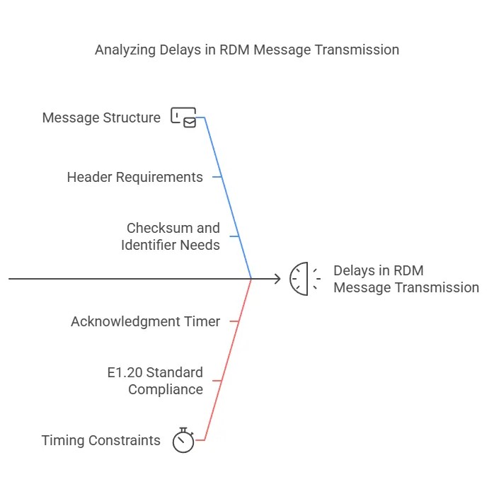
3. Decoding the Minimum Message Structure
Every RDM packet includes headers, checksums, and identifiers. Even a basic “ping” command, such as GET_PARAMETER, requires the following:
- Start Code: 1 byte
- Sub-Start Code: 1 byte
- Message Length: 1 byte
- Destination UID: 6 bytes
- Source UID: 6 bytes
- Transaction Number: 2 bytes
- Port ID: 1 byte
- Command: 1 byte
- Parameter ID: 2 bytes
- Checksum: 2 bytes
These components alone total 21 bytes, without including any payload data.
4. The Role of Timing Constraints in RDM Communication
The E1.20 standard mandates strict timing to prevent data collisions. After sending a request, the controller must wait for an ack_timer response (at least 1.3 milliseconds) before releasing the line. Devices have up to 2 milliseconds to respond. If a device misses this window, the controller interprets it as a lack of response.
5. Key Timing Values in RDM Systems
| Parameter | Minimum | Typical | Maximum |
|---|---|---|---|
| Controller ack_timer | 1.3 ms | 2 ms | 10 ms |
| Device response time | 0 ms | 1 ms | 2 ms |
| Break time | 176 µs | 176 µs | 352 µs |
These timing values highlight a fundamental challenge in RDM: while the protocol can theoretically support rapid 1.3-millisecond turnarounds, practical factors such as cable length, device firmware, and network interference often extend response times closer to 2 milliseconds.
6. Speed vs. Reliability: The RDM Trade-Off
While shorter messages enhance efficiency, RDM prioritizes reliability. This creates a trade-off:
- Faster Responses: A 1.3-millisecond ack_timer allows controllers to poll devices quickly, which is crucial for time-sensitive operations like emergency stops.
- Stability Risks: Pushing timing limits increases the likelihood of missed responses, especially in noisy environments or with older, slower devices.
For instance, if a fixture requires 1.5 milliseconds to process a request, a controller set to 1.3 milliseconds will incorrectly assume it is offline. This is why most systems default to 2 milliseconds, striking a balance between speed and tolerance for real-world conditions.
7. Testing the Limits: Determining Optimal Timing for Your Setup
To test your specific setup and determine the optimal timing, follow these steps:
- Use an RDM Analyzer: Tools like Open Lighting’s OLA enable you to send custom packets and measure response times.
- Start Small: Send a basic GET_DEVICE_INFO command (24 bytes) and gradually reduce the ack_timer until responses are missed.
- Check the Logs: If you observe missed replies, increase the timer value.
Modern LED fixtures may provide stable replies at 1.5 milliseconds. However, integrating older devices, such as a dimmer rack from the 1990s, may require a higher minimum value for reliable operation.
8. RDM and DMX: Understanding Their Relationship
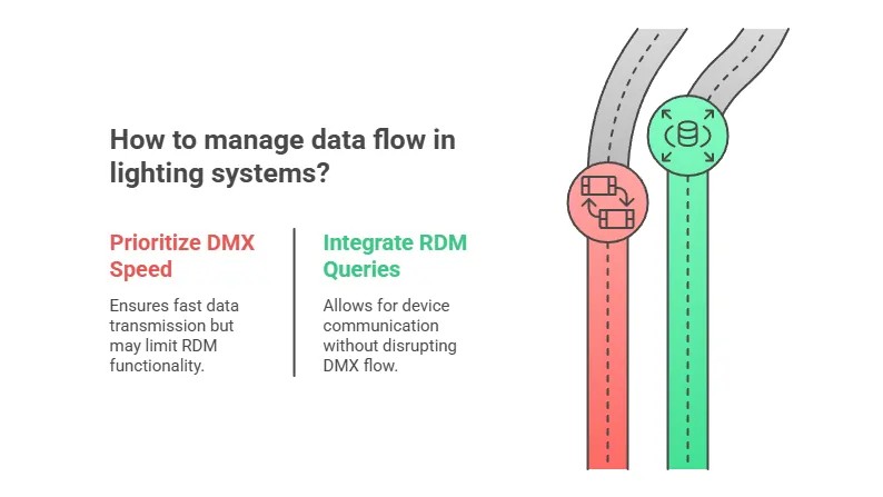
A standard DMX512 packet sends 512 channels every 44 milliseconds, providing rapid updates. RDM messages, however, interrupt this flow. Sending frequent RDM requests can reduce DMX’s refresh rate.
However, RDM does not replace DMX; it operates alongside it. NULL START Code packets maintain DMX data flow while RDM queries run in the background.
9. The Future of RDM: Exploring Sub-Millisecond Communication
With the rise of IoT and smart venues demanding faster systems, the possibility of sub-1-millisecond RDM messages is being explored. While the E1.20 standard could evolve, physical limitations present significant challenges:
- Signal Travel Time: Even at the speed of light, a 300-meter DMX line introduces a 1-microsecond delay.
- Device Processing: Lower-cost microcontrollers may require more time to process packets.
Currently, 2 milliseconds remains the practical minimum. As controllers become more sophisticated and devices more responsive, this may change.
10. Why the Shortest RDM Message Matters: Optimizing Performance
The pursuit of the shortest RDM message is critical for optimizing systems that operate under pressure. Whether you’re managing a Broadway show or a museum installation, understanding these limits helps you design lighting rigs that are both fast and reliable.
Remember, even the smallest message can have a significant impact on overall system performance.
Frequently Asked Questions About RDM Messages
1. What is the shortest RDM message practically possible?
The shortest RDM (Remote Device Management) message, as defined by the E1.20 RDM standard, is theoretically minimal but not practical for real-world applications. This minimum message is composed of only a few bytes, primarily including the start code and message length. However, this form lacks essential information needed for any meaningful control or feedback. In practice, a functional RDM message requires additional bytes to specify the source and destination, command details, and checksum for error detection, which significantly increases its size.
2. How does a typical RDM message differ in size from the shortest possible message?
A typical RDM message is considerably larger than the theoretical shortest message. While the shortest RDM message might consist of just 2 or 3 bytes, a standard operational RDM message generally ranges from 24 to 255 bytes. This difference arises because a typical message includes various fields necessary for proper device management, such as:
- Start Code (1 byte): Identifies the beginning of an RDM message.
- Destination UID (6 bytes): Specifies the unique identifier of the target device.
- Source UID (6 bytes): Specifies the unique identifier of the sending device (usually the controller).
- Command Class (1 byte): Indicates the type of command being issued.
- Parameter ID (2 bytes): Identifies the specific parameter being queried or set.
- Data Field (variable length): Contains the actual data related to the command.
- Checksum (2 bytes): Ensures the integrity of the message by allowing error detection.
These additional fields are essential for RDM’s functionality, enabling tasks such as device discovery, parameter setting, and status reporting.
3. What essential components are included in the shortest functional RDM message?
For an RDM message to be functional, it must include a set of essential components that enable devices to communicate effectively. The key components of a minimal functional RDM message include:
- Start Code: Marks the beginning of the RDM packet.
- Sub-Start Code: Differentiates RDM packets from standard DMX packets.
- Message Length: Specifies the total length of the RDM message, ensuring that the receiving device knows how many bytes to expect.
- Destination UID: Identifies the specific device that the message is intended for.
- Source UID: Identifies the device sending the message, typically the controller.
- Transaction Number: Helps match responses with their corresponding requests.
- Command Class: Indicates the type of operation to be performed (e.g., get parameter, set parameter).
- Parameter ID: Specifies the specific parameter to be accessed or modified.
- Data: Contains the actual data being sent to the device, if required by the command.
- Checksum: Ensures the integrity of the message, allowing the receiver to verify that the message was not corrupted during transmission.
Without these components, an RDM message would be incomplete and unusable for device management.
4. Is it possible to use the shortest RDM message for practical lighting control applications?
No, it is not feasible to use the shortest possible RDM message for practical lighting control applications. The theoretical minimum RDM message lacks the necessary information to perform any meaningful control or monitoring functions. Practical applications require the inclusion of destination and source identifiers, command codes, parameter IDs, and data fields, all of which increase the message size significantly.
For example, setting the intensity of a light fixture requires an RDM message that includes the destination UID of the fixture, a command to set a parameter, the specific parameter ID for intensity, and the desired intensity value. All of these elements add to the message size, making it much larger than the theoretical minimum.
5. How does the E1.20 RDM standard define the structure of RDM messages, and what are the key considerations for message length?
The E1.20 RDM standard precisely defines the structure of RDM messages to ensure interoperability and reliable communication between devices. The standard specifies the order and format of each field within the message, including start codes, identifiers, command classes, parameter IDs, data fields, and checksums.
Key considerations for message length within the E1.20 RDM standard include:
- Minimum Length: The standard defines a practical minimum length that includes all essential fields for device communication.
- Maximum Length: The standard also sets a maximum length to prevent excessively long messages that could disrupt network performance.
- Variable Length Data: The standard allows for variable-length data fields to accommodate different types of commands and parameters, providing flexibility while maintaining structure.
- Checksum: The standard requires a checksum field to ensure message integrity and error detection.
The structure defined by the E1.20 RDM standard ensures that all RDM-compliant devices can correctly interpret and respond to messages, facilitating effective remote device management.
6. What is the impact of message length on RDM communication speed and reliability?
The length of RDM messages has a direct impact on the communication speed and reliability of RDM systems. Shorter messages generally result in faster communication, as they require less time to transmit and process. This can be particularly important in time-sensitive applications where quick responses are needed. However, excessively short messages that omit essential information are not useful.
Longer messages, while providing more comprehensive information, can increase the risk of transmission errors and slow down communication. The E1.20 RDM standard addresses this trade-off by defining a structured message format that balances the need for comprehensive data with the need for efficient communication. The checksum field, included in all RDM messages, helps ensure reliability by allowing devices to detect and discard corrupted messages.
7. Are there any strategies to optimize RDM message length for specific applications?
Yes, there are several strategies to optimize RDM message length for specific applications, balancing communication speed and data requirements:
- Use Efficient Parameter IDs: Select parameter IDs that convey the necessary information in the fewest bytes possible.
- Minimize Data Field Size: Use the smallest data types that can accurately represent the required values. For example, use 8-bit values instead of 16-bit values when the full range is not needed.
- Group Related Commands: Combine multiple related commands into a single RDM message when possible to reduce overhead.
- Implement Data Compression: For applications that require transmitting large amounts of data, consider using data compression techniques to reduce the size of the data field.
- Optimize Polling Frequency: Adjust the frequency at which devices are polled to balance the need for up-to-date information with the need to minimize network traffic.
By implementing these strategies, it is possible to optimize RDM message length for specific applications, improving communication speed and overall system performance.
8. How does the ack_timer affect the minimum RDM message size in practical applications?
The ack_timer, which stands for acknowledgment timer, plays a crucial role in determining the minimum usable RDM message size in practical applications. The ack_timer is the amount of time a controller waits for a response from a device after sending an RDM command. This timer is essential to ensure that the controller does not prematurely assume a message has been lost or ignored.
The length of the ack_timer directly influences the minimum RDM message size because it impacts the overall timing constraints of the communication. If the ack_timer is set too short, devices may not have enough time to process the message and respond before the controller times out. On the other hand, if the ack_timer is set too long, it can slow down the entire communication process.
In practice, the minimum RDM message size must be large enough to accommodate the essential information needed for the device to understand and respond to the command within the ack_timer window. This includes the start code, destination and source identifiers, command codes, parameter IDs, and any necessary data.
9. What are some common tools for analyzing and testing RDM message timing and length?
Several tools are available for analyzing and testing RDM message timing and length, ensuring optimal performance and reliability. Some common tools include:
- RDM Analyzers: Dedicated RDM analyzers, such as those from Obsidian Control Systems and RDM Protocol, provide detailed insights into RDM communication, allowing users to view message timing, length, and content in real-time.
- DMX/RDM Software: Software applications like Open Lighting Architecture (OLA) and LightShark offer RDM analysis and testing capabilities, enabling users to send custom RDM commands, monitor responses, and measure timing parameters.
- Oscilloscopes: Oscilloscopes can be used to measure the electrical characteristics of RDM signals, providing precise timing measurements and allowing users to identify signal integrity issues that could affect communication reliability.
- Logic Analyzers: Logic analyzers can capture and analyze the digital signals transmitted over DMX/RDM networks, providing detailed information about message content and timing.
- Custom Test Scripts: Custom test scripts can be written using programming languages like Python or Lua to automate RDM testing and analysis, allowing users to perform repeatable tests and generate detailed reports.
These tools enable lighting professionals and developers to thoroughly analyze and test RDM message timing and length, ensuring that their systems are performing optimally.
10. How can understanding the shortest RDM message help in troubleshooting lighting control systems?
Understanding the shortest RDM message can be invaluable in troubleshooting lighting control systems. By knowing the minimum message size and essential components, technicians can quickly identify potential issues that may be causing communication problems.
For example, if a lighting fixture is not responding to RDM commands, technicians can use an RDM analyzer to examine the messages being sent to the fixture. If the messages are shorter than the minimum expected size or if they are missing essential components, it could indicate a problem with the controller, cabling, or the fixture itself.
Additionally, understanding the ack_timer and its relationship to message size can help troubleshoot timing-related issues. If the ack_timer is set too short, it could cause the controller to prematurely time out, even if the fixture is functioning correctly. By adjusting the ack_timer, technicians can often resolve these types of issues.
In summary, a thorough understanding of the shortest RDM message and its essential components can significantly aid in troubleshooting lighting control systems, enabling technicians to quickly identify and resolve communication problems.
Need more answers? Ask your question for free at WHAT.EDU.VN. Our experts are ready to provide fast, accurate, and helpful information. We’re located at 888 Question City Plaza, Seattle, WA 98101, United States. Contact us via Whatsapp at +1 (206) 555-7890 or visit our website at WHAT.EDU.VN.
Don’t struggle with unanswered questions. Visit what.edu.vn today and get the answers you need, absolutely free. Our community is waiting to help!